🏗️ Assembly
Soldering
Important
Please note that some components in this board need to be soldered.
The Smart Powermeter comes as a set consisting on a SMD pre-soldered board to which you will need to mount the following components:
HLK-2M05 power module, a 2W AC-DC step-down switching power supply module THT solderable.
A 2-Pin 2mm-pitch screw terminal block, for the AC power imput, also THT solderable.
Note
When buying the Smart Powermeter read the product description to make sure these two components are included, otherwise you might need to get them on your own.
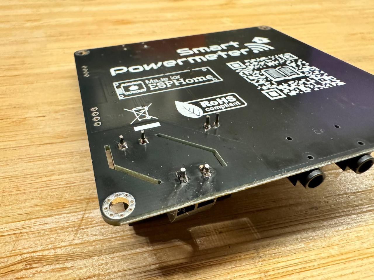
The soldering of these two components is quite fast, just make sure not to bend any of the power supply module pins. If you have never soldered or you want to improve your soldering techniques I recommend you the Adafruit Guide To Excellent Soldering
Desoldering
If you ever need to desolder any burdern resistor, for instance, when opting for a different CT clamp on that channel, simply apply heat and remove it carefully.
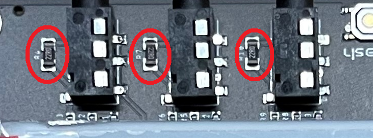
Assembly
Once the board is fully soldered, it’s time to mount the e-paper display (in case you are using this accessory to display real-time information):
Open the clamp connector, by smoothly pulling up the tab.
Introduce the e-paper FPC with the exposed pads facing down (against the PCB)
Close the clamp connector
Bend carefully the e-paper’s FPC in a way that the panel rests over the PCB. Add a very small piece of double-side tape on the rear to fix it.

Last but not least, it is highly recommended to mount the Smart Powermeter on an enclosure (like the suggested Enclosure) to prevent unintended contacts between the bottom side of the board (since the hig-voltage pins are exposed).